Tag: se

Nexstar SE Wedge

The final part of my Nexstar project was getting it on a wedge which would make auto-guided long exposure shots possible. Unfortunately, the Nexstar wedge has long since been discontinued and even if it hadn’t — $160 for a weenie little wedge for this scope was a bit much for me. So I decided to buy a cheap used wedge from an older Celestron system and make whatever modifications were needed to get it to work with the Nexstar.

What I didn’t expect was how little modification was needed to get an old 1980’s era Celestron C8 wedge to work with the Nexstar SE. All the holes, both on the tripod and drive base lined up perfectly and the only modification I really had to make to the wedge was to hammer out the center guide peg.
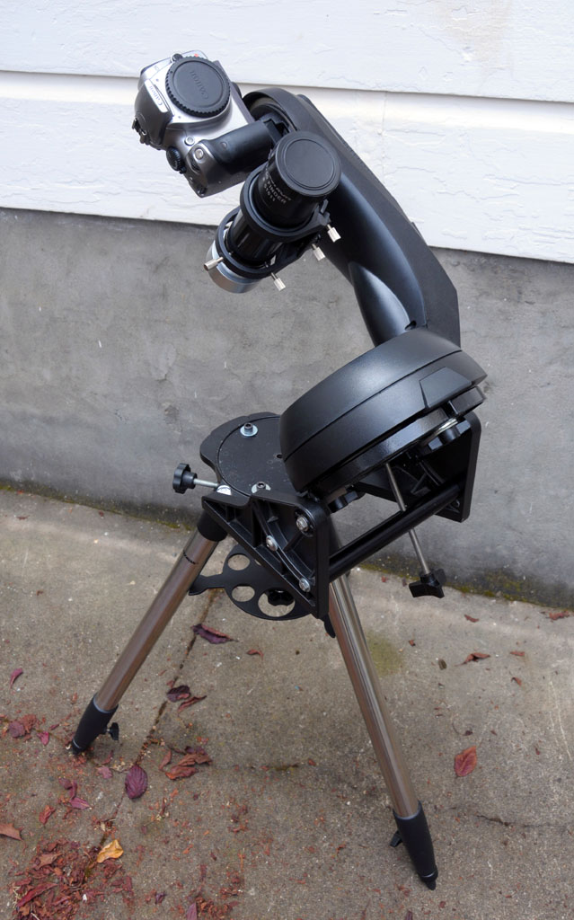
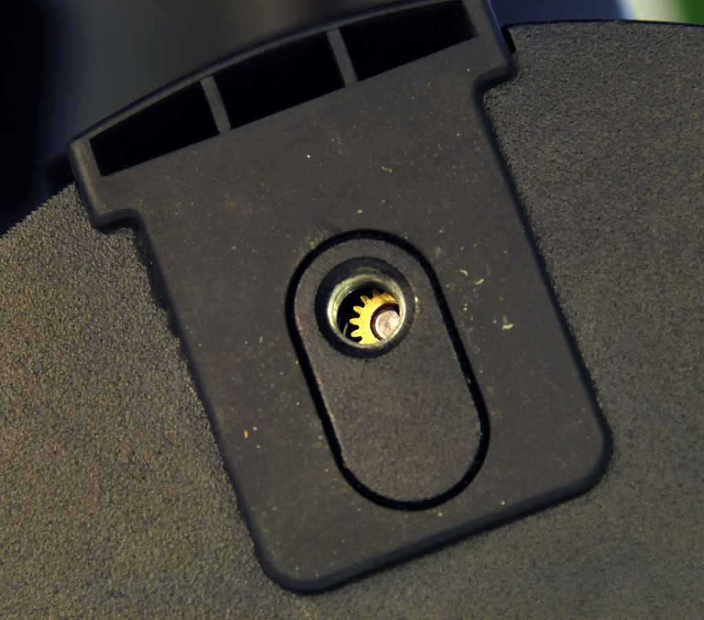
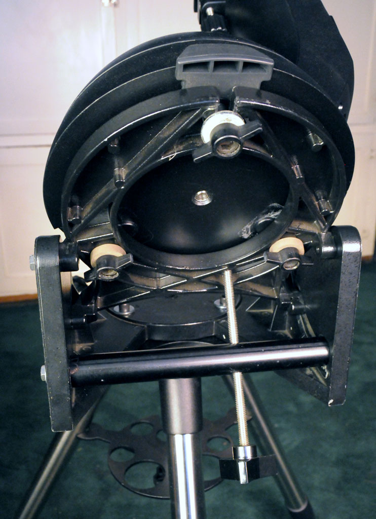
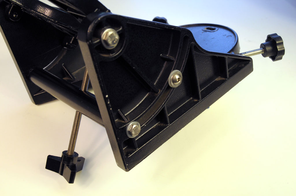
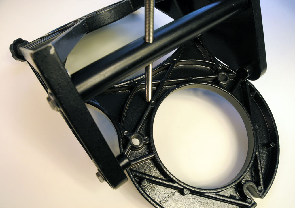
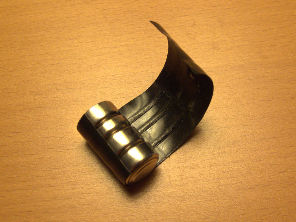
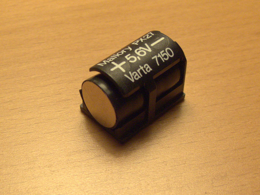
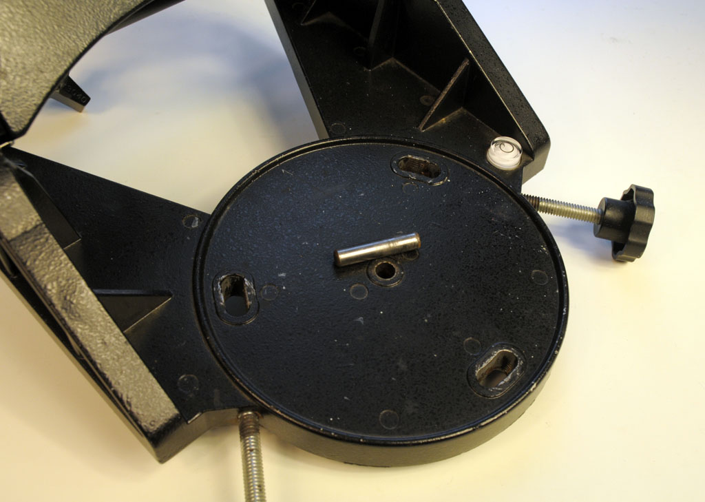
Mounting the Nexstar

In the first photo on the right, the wedge with the center peg removed has been mounted on the Nexstar SE tripod. The center peg on the tripod fits well as it is much smaller than the space left by the removed wedge peg. The tripod bolts hold everything in alignment and there is little to no lateral movement of the wedge in relation to the tripod. The bolts are 5/16″ x 24 x 1.5″ cap screw bolts from the local hardware store. The azimuth adjusters work perfectly with this setup as long as you don’t tighten down the cap screw bolts too much.

One rather major item of caution is the length of the bolts that attach the Nexstar drive base to the wedge. Inside the drive base is a gear (right under the fork arm) that rides very close to the opening for the mounting bolts and is completely unprotected. (Seen in the 2nd photo.) If a bolt is too long and protrudes very far inside the telescope, this gear will bind against the mounting bolt probably causing damage to the drive base. These bolts are 3/8 x 16 — I got lucky and had an extra set from my old Losmandy GM-8 that were the right size but much too long. I cut and sanded them with a Dremel and then added some thick washers just to be extra careful. The final image on the right shows underside of the wedge with the Nexstar mounted.

Another modification I made was to remove two of the rubber feet from the Nexstar base to allow for more latitude range before the Nexstar base impacts with the side of the wedge as the drive base is slightly wider than the wedge. With the rubber feet removed I can get the latitude all the way to the 14 degree mark before the base connects with the wedge — with the rubber feet on, this was more like 30 degrees. The rubber feet peel off without too much difficulty and if I ever what them back on, they’re easy to reattach with some rubber cement glue. (I left one of the rubber feet on to designate the ‘top’ of the mount.)
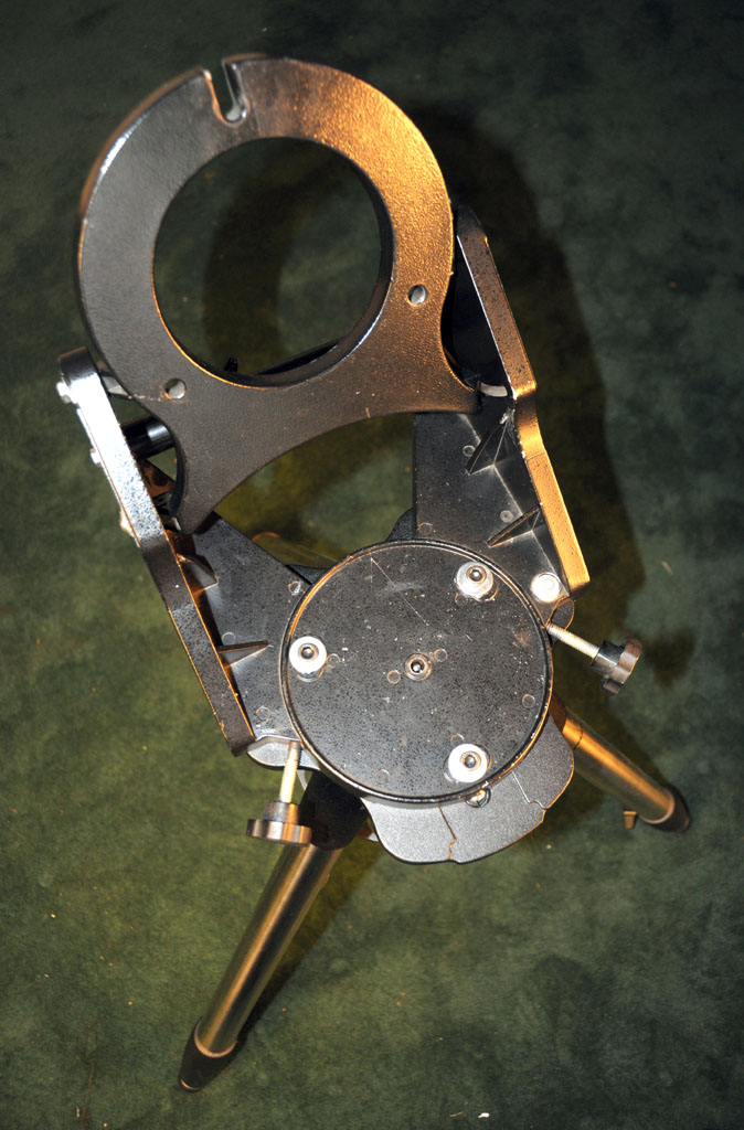
Adding a Latitude Adjuster

My very first telescope back in 1999 was a Meade LX50 on which one of the first modifications I made to it was upgrading the rather flimsy wedge latitude adjuster that came with that scope. Since then I’ve had the old adjuster kicking around from box to box mainly because I’m a pack-rat but now I’m glad I never threw it away! The length of the bar turned out to be too long for the Celestron wedge by only about 3mm. I cut and sanded the bar down to size with Dremel cutting and grinding disks (at one point I had to wear work gloves because of how hot the bar was getting!) until it was a snug fit and then ‘painted’ any visible scuffs with a black Sharpie. The end result almost looks like it was meant to be there. 😉

Once down to size, I fixed the bar in place to the lowest point on the latitude guide groove on the wedge with a couple of bolts and washers to hold it in place. The long latitude adjustment screw fits well to the underside of the wedge and since this setup is not going to take a bunch of weight (certainly much less than the LX50 it was originally designed for!) it works very nicely. This modification also added a great deal of stability to this wedge. I was lucky to have saved the LX50 latitude adjuster and I think that even if I didn’t have it, I would have eventually wound up trying to make something similar out of wood.

One thing I’d eventually like to add is a pair of knobbed bolts in place of the current cap-screw bolts I have for the latitude adjustment on each side of the wedge so I can loose the allen wrench I currently have to use to loosen them.
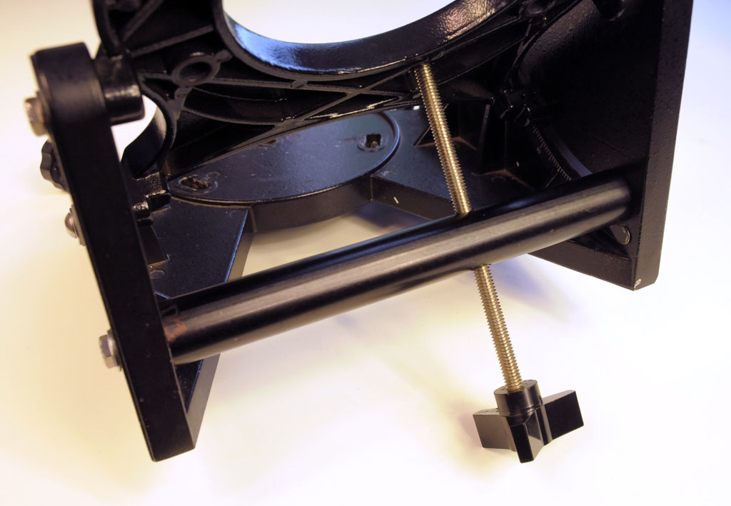

Nexstar SE Camera Platform

I recently picked up a used Nexstar 6/8 SE mount and tripod with the idea of using it not only as a grab-and-go for my 72mm f/6 Orion EON (and hopefully a 5 or 6″ SCT OTA down the line) but also in the hopes of using it for some lightweight wide-field long-exposure and time-lapse astrophotography.

I wanted to side-by-side mount a DSLR camera and wide-angle lens combo alongside my unused Celestron 9×50 finderscope from my CPC800 and use an Orion Starshoot autoguider attached to the finder to guide the whole contraption for long exposure photos. That this setup can run on batteries and is lightweight enough to chuck in the back of the car for camping trips made this a really interesting camera platform despite the Nexstar’s well known astrophotography limitations.


Celestron 9×50 Finderscope Autoguider

I found a few pages and forum posts (http://bit.ly/N5GJ7D, http://bit.ly/QoZl9f and http://bit.ly/MUgGDD) with instructions on making an adapter for Orion’s autoguider using PVC pipe fittings but unfortunately all of them required drilling a hole in the finder which I didn’t want to do. I wanted a solution which would require no modifications to the finder and would be easy to undo.

Luckily, while fooling around with the finderscope one afternoon I realized that the threads on the back of Celestron’s 9×50 Model # 51611 finderscope that the cross hair eyepiece attaches to are common 2″ SCT threads! Given that the 1.25″ adapter on the Starshoot autoguider attaches to a standard T-thread on the autoguider body all I needed to find was a male SCT to male T-thread adapter to fit everything together.

I had no clue if such a beast existed and after a little bit of googling I found what I needed at http://agenaastro.com — their Blue Fireball T / T2 Male Thread to SCT Male & M48 was exactly what was needed to make this work. (Seen in the first photo on the right.) This adapter is very low profile and easily allows the finderscope to achieve infinity focus with the Starshoot autoguider.

As shown in the middle and bottom photos on the right, the whole thing comes together in a nice, compact and sturdy assembly and it fits perfectly on the standard Celestron finderscope mount with no modifications needed.

Side-by-Side Camera/Autoguider Mount

Next up was finding a sturdy way to mount the finderscope and camera on the Nexstar.

From a previous project I had a mounting bar with a center hole tapped for a standard 1/4-20 tripod stud with 4 untapped holes on each side. A couple of bolts and washers from the local hardware store worked to mount the Celestron 9×50 finder mount securely to the bar.

To attach the whole thing to the Nexstar, I used the mounting block from the Orion EON 72mm f/6. (Which normally rides piggyback on my CPC800.)

The second photo shows the system all set up with the finderscope, Starshoot autoguider and an IR modified Canon 300D. One of the lenses I plan to use with this setup is a Zenitar 16mm fisheye but unfortunately, the finderscope is mounted so far forward that it projects into the Zenitar’s 180 degree field of view. So I’ll either need to crop the resulting images or figure out some way of mounting the camera further forward or the finderscope further back.

The last image shows everything attached to the Nexstar SE mount and ready to go. Note that I did have to remove the plastic altitude gear covering for the side-by-side mounting to fit which detracts a bit from the looks but everything still works fine.

I love how compact and multi-functional this setup is and can’t wait to get some time out in the field with it. Running with rechargeable batteries for the mount and with spare batteries for the camera and my netbook I think I can get a solid evening of imaging with this setup without ever needing a power plug.

The next step was to adapt a cheap, old wedge for the Nexstar


Rollei 35 TE Repairs

I bought a Rollei 35 TE recently that had a couple of issues and it was driving me bonkers that I could find very little information online about this great camera. Everything I could find, including the service manual, was for the previous generation 35, S and T series cameras.

The issues with my TE were in the meter and lens barrel. The lens barrel was loose and when retracted the lens kept flopping out. (This is common ailment with all Rollei 35 cameras.) The other problem was that the meter would not auto-off after 10 seconds as stated in the manual. It was always on as long as there was a battery in the chamber.

Metering was spot on and agreed perfectly with my Gossen Lunasix3 and the camera still took a great picture despite these issues but they were quickly becoming a major annoyance. Since all the repair estimates I got were for much more than what the camera cost me (and often more that what I could realistically sell it on eBay for) and did not guarantee the meter could be repaired or replaced (in fact most were convinced it could not) I decided to try to fix it myself and document the process for others that might be facing the same issues.

For those doing a repair and in need of extra detail, you can see the full size versions of all the photos in this post by following this link.

Jump Straight to:
 Disasembly / Reassembly
Repairs – Meter Does Not Turn Off
Repairs – Loose Lens Barrel
Easy Battery Solution

Disassembly / Reassembly

I started with the film advance crank removal as this is usually where I have the most difficulty. In this case the crank cover scew came off without too much force. Underneath it is a small copper washer and the crank itself held in place by three screws as seen in the photo here.

Next there are 2 philips-head screws on either side of the camera and the rest is on the back: the battery lever cap, another flat-topped screw in the middle of the camera and the rewind lever. The rewind lever has a collar underneath the tab as seen in the 2nd photo.

At this point the top cover is not yet ready to be removed as it will not come off without first removing the rewind pin which is held in place by a spring. If you look closely at the rewind pin, you will notice that it has a flat side at half-way between the up and down positions. The pin needs to be turned half-way so the flat side is against the spring so it can be pulled straight out. Use a very small pliers and you may need to use the tip of an x-acto blade to push spring out of the way. Only once pin is removed can the top cover can be pulled off without damage.

In the 3rd photo the top cover has been removed and you can see the rewind pin, the retaining spring and the position the pin needs to be in for removal.

When reassembling the camera, there is trick to getting the pin back in place properly. The rewind pin pushes up a metal rod inside the camera (seen in the final photo) that unlocks the film sprocket (the toothed wheel that the 35mm holes fit in to directly below it) allowing the film to be rewound.

Use small screwdriver to push inner rod up and it will lock in place. This is the only way the rewind pin will fit in back in. The rod will pop back down when you rotate the film sprocket by hand. Try this a couple of times before attempting to put the top cover on. Again, you may need to use the tip of an x-acto bade to push the spring out of the way when reassembling.

Once completed, replace the rewind collar and lever, screw it in place and test it out before finishing reassembly.

Here are a few more detail photos of the camera without the top cover:

Repairs – Meter Does Not Turn Off

This was what led me to do this surgery on the camera in the first place as I found it a real pain having to pop-in, pop-out the battery all the time. A quick test roll showed that the metering was great (I had already checked it against my Gossen Lunasix3) and it could take a great pic, but the auto-off issue was keeping from using the camera effectively.

As soon as I pulled the top cover off I noticed some dry, white powdery gunk under the white wire on the circuit board as seen in the photo here. I scraped it off the circuit board between solder joints with tip of small flat-head screwdriver and happily (amazingly!) the meter immediately started functioning as it should with auto-off after 10 seconds. I figure this was corrosion of some sort that was causing a short and preventing the meter from turning off.

Repairs – Loose Lens Barrel

This was the only issue that I could find any information about online as apparently affects a lot of Rollei 35’s. Unfortunately, the fix requires breaking down the camera even further to replace a friction collar inside the camera body and I really didn’t want to go to those lengths as all those mechanical bits looked like a little more than I knew how to deal with.

Instead I had the idea of going in through the front of the camera between the lens barrel and the collar that holds it in place. Whatever I used needed to be adhesive on one side so it could stick to the inside of the lens collar and stay in place. I tried some flocking paper left over from another project but it was way too thick and after a little experimenting discovered that a simple yellow Post-It was the perfect solution — it was just the right thickness and the adhesive was not too so strong as to make it difficult to work with.

I cut off the the adhesive strip from a fresh Post-It and trimmed it so it was about 1.5cm wide. With the camera fully assembled and the lens locked in place, I slid the Post-It between the lens barrel and collar with adhesive side outward against the lens collar and worked it into the camera af far as it would go. This should only be about 2-4mm. I found the best place on my Rollei was at about the 2 o’clock position of the lens barrel. Once the Post-It was in postion, I folded it down against the body of the camera, unlocked the lens and slid it in and out to test if the friction was enough to hold the lens and if the paper would stay in place. Once I was satisfied with the positioning, I used an x-acto knife to trim off the excess paper and then a black sharpie to paint over yellow Post-It color.

This method worked perfectly for me producing exactly the right friction to hold the lens and is still in place showing no signs of causing any other issues. Also, once touched up with a black sharpie, you can’t see it unless you really look…

Easy Battery Solution

The best, cheapest battery tip I have found for the Rollei 35 TE and SE cameras came from this flickr discussion [Thank you nadameansnothing!]:

http://www.flickr.com/groups/rollei35/discuss/72157622459831809/

Basically, the idea is to use three LR44 batteries and one LR43 battery wrapped in electrical tape to hold them together. With the thinner LR43 in the set the length is perfect and you can wrap enough tape around them to increase the diameter until you get a snug fit in the holder. (I didn’t bother and it works fine.) Best of all, these batteries are easy to find, comparatively cheap and they last forever.

All together they produce 6V but the TE / SE meters don’t seem to mind the slight over-voltage as much as the previous generation meters did. So it’s not strictly necessary, but you can use a single depleted cell in the set to get closer to the camera’s native 5.6V. I haven’t really noticed a difference either way.


Copyright © 1996-2010 astroturtle. All rights reserved.
Jarrah theme by Templates Next | Powered by WordPress